3.1.6.37. QzLiq1 Material
The command constructs a uniaxial q-z material that incorporates liquefaction effects. This q-z material is used with a zeroLength element to connect a pile (beam-column element) to a 2 D plane-strain FE mesh. The q-z material obtains the average mean effective stress (which decreases with increasing excess pore pressure) from two specified soil elements or from the mean effective stress provided explicitly as a timeseries data. Currently, in order to compute the mean effective stress from connected elements, the implementation requires that the specified soil elements consist of FluidSolidPorousMaterials in FourNodeQuad elements.
- uniaxialMaterial QzLiq1 $matTag $soilType $tult $Z50 $suction <$c> $alpha $ele1 $ele2
- uniaxialMaterial QzLiq1 $matTag $soilType $tult $Z50 $suction <$c> $alpha -timeSeries $tag
Argument |
Type |
Description |
|---|---|---|
$matTag |
integer |
integer tag identifying material |
$soilType |
integer |
= 1 or 2. (see notes of QzSimple1 Material) |
$qult |
float |
Ultimate capacity of the q-z material. |
$Z50 |
float |
Displacement at which 50% of qult is mobilized in monotonic loading. |
$suction |
float |
Uplift resistance is equal to suction*qult. |
$c |
float |
The viscous damping term (dashpot). |
$alpha |
float |
The exponent \(\alpha\) defines the extent of non-linearity in element’s capacity and stiffness with excess pore pressure ratio (\(r_u\)). See description below. |
$ele1 $ele2 |
integer |
are the eleTag (element numbers) for the two solid elements from which QzLiq1 will obtain mean effective stresses and excess pore pressures. |
$seriesTag |
integer |
alternatively mean effective stress can be supplied by a time series by specifying the text string -timeSeries and the tag of the series $seriesTag. (see Time Series Command) |
To model the effects of liquefaction with QzLiq1, it is necessary to use the material stage updating command:
- updateMaterialStage –material matNum –stage sNum
Argument |
Type |
Description |
|---|---|---|
$matNum |
integer |
material number (for QzLiq1) |
$sNum |
integer |
desired stage (valid values are 0 & 1). |
Note
With sNum=0, the QzLiq1 behavior will be independent of any pore pressure in the specified solidElem’s.
When updateMaterialStage first sets sNum=1, QzLiq1 will obtain the average mean effective stress in the two solidElem’s and treat it as the initial consolidation stress prior to undrained loading. Thereafter, the behavior of QzLiq1 will depend on the mean effective stresses (and hence excess pore pressures) in the solidElem’s.
The default value of sNum is 0 (i.e., sNum=0 if updateMaterialStage is not called).
Note that the updateMaterialStage command is used with some soil material models, and that sNum=0 generally corresponds to the application of gravity loads (e.g., elastic behavior with no excess pore pressure development) and sNum=1 generally corresponds to undrained loading (e.g., plastic behavior with excess pore pressure development).
QzLiq1 inherits QzSimple1 and modifies its response based on the mean effective stresses (and hence excess pore pressures) in the specified solid soil elements. The logic and implementation are the same as for how TzLiq1 Material inherits and modifies TzSimple1 Material.
The constitutive response of QzLiq1 is taken as the constitutive response of QzSimple1 Material scaled as a non-linear function of free-field excess pore pressure ratio \(r_u\) determined from the mean effective stres calculated from the solid soil elements or obtained from the specified time series data. The ultimate capacity (\(q_{ult}\)) and tangent modulus in liquefied soil are scaled by a factor of \((1-r_u)^\alpha\), where \(\alpha\) is a constant. For modeling tip capacity of piles in liquefiable soils, the exponent \(\alpha\) can be determined from the drained soil friction angle \(\phi'\) as
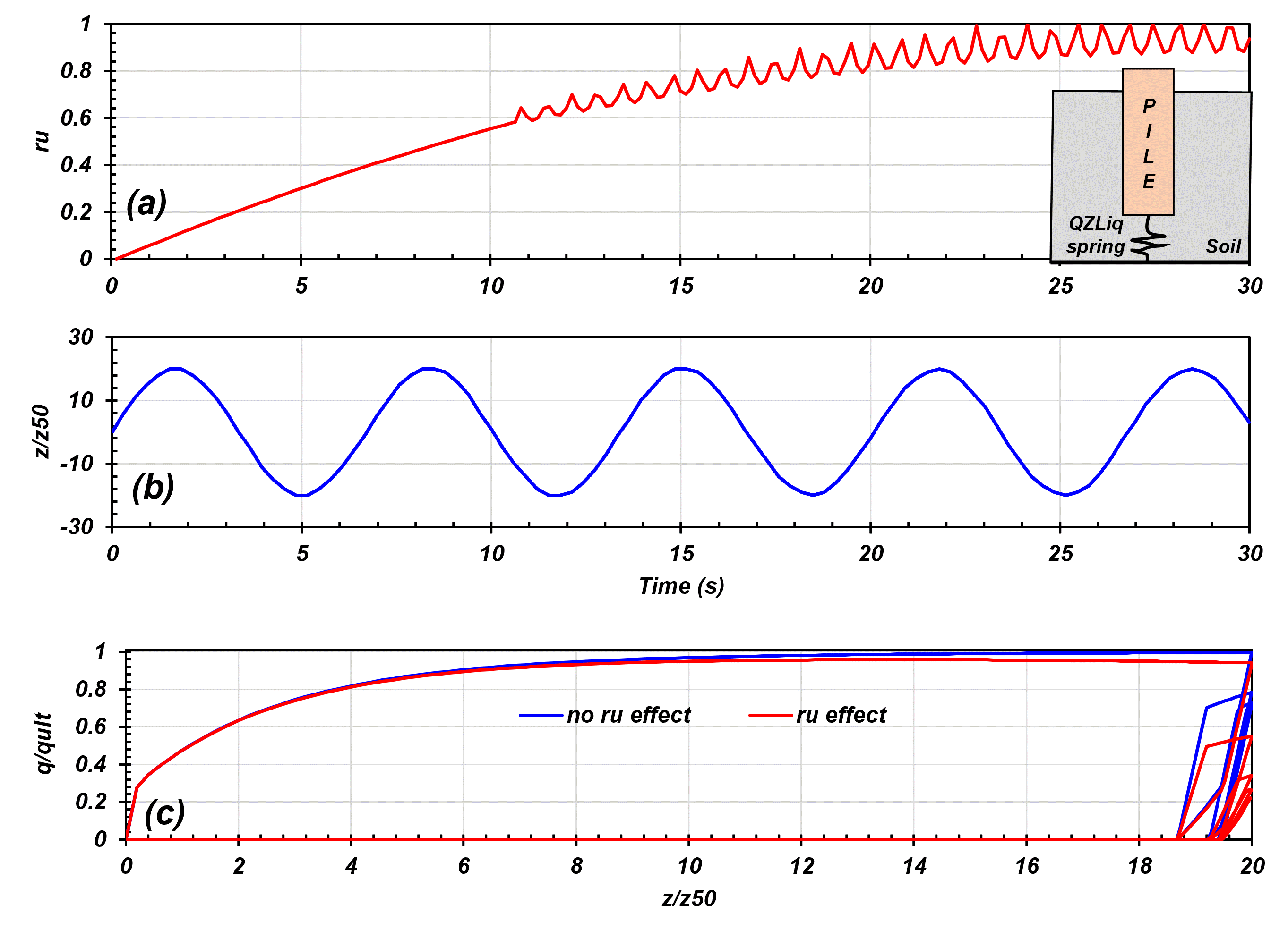
The QzLiq1 material behaves identically to the QzSimple1 material if there is no excess pore water pressure (i.e., sNum = 0 or \(r_u=0\)). If \(\alpha=1.0\), the ultimate capacity and stiffness of the QZLiq1 spring will depend linearly on the mean effective stress of the soil similar to PySimple1 Material and TzSimple1 Material materials. The behaviour of Qzliq1 material in presense of excess pore pressure in soil is shown in Fig. 3.1.6.19. Another example illustrating the use of QzLiq1 material for modeling tip capacity in liquefiable soils is presented in Fig. 3.1.6.20.

Fig. 3.1.6.19 QZLiq material response “with \(r_u\)” and “no “\(r_u\)” effect during cyclic loading.
Example 1: QZLiq material response “with \(r_u\)” and “no \(r_u\)” effect during cyclic loading| QZLiqExample.py
Fig. 3.1.6.19 shows the material response of QZLiq1 spring in the presence of excess pore pressure in the soil. The model consisted of a movable pile node and a fixed soil node. The excess pore pressure ratio \(r_u\) calculated from the mean effective stress applied to the QZLiq spring is shown in Fig. 3.1.6.19 (a). In the model, a cyclic loading [Fig. 3.1.6.19 (b)] was applied on the pile node, and the response of QZLiq spring was recorded for the case of “no \(r_u\) effect” and “with \(r_u\) effect”.
In the first case, “no \(r_u\) effect”, the QZLiq spring behaved independently of excess pore presses in soil (i.e, sNum=0). As expected, the cyclic response of the QZLiq material was similar to QZSimple material. In the second scenario, “with \(r_u\) effect”, the QZLiq material response was affected by the excess pore pressure ratio \(r_u\) in soil. As excess pore pressure (or \(r_u\)) increased in soil, the capacity and stiffness of the QZLiq spring decreased nonlinearly as \((1-r_u)^\alpha\). In the first cycle, at about \(t \approx 2 sec\), with excess pore pressure ratio of \(r_u \approx 0.1\), \(z/z_{50} \approx 20\), and \(\alpha = 0.55\), the ultimate capacity of the QZLiq spring decrased to about \(95 \% q_{ult}\). In the second cycle, at about \(t \approx 8.5 sec\), with excess pore pressure ratio of \(r_u \approx 0.5\) and \(z/z_{50} \approx 20\), the mobilized resistance of the QZLiq spring decreased to about \(70 \%\) of the mobilized resistance (\(q/q_{ult}\approx0.8\)) for the case of “no \(r_u\) effect” i.e. it became equal to about \(55\% q_{ult}\) [Fig. 3.1.6.19 (c)]. When the soil nearly liquefied \(r_u\geq0.95\), the QZLiq capacity and stiffness approached zero.

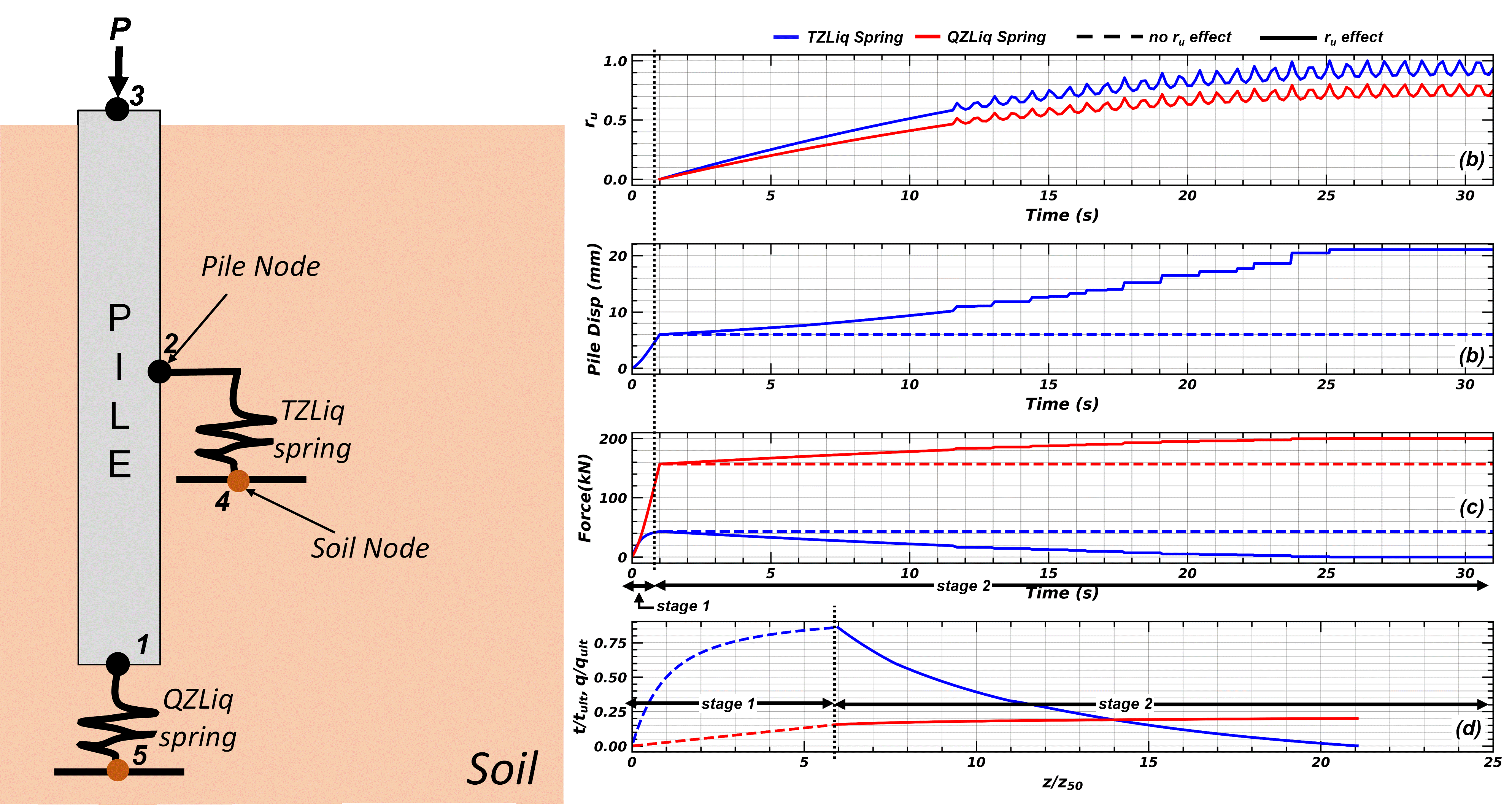
Fig. 3.1.6.20 Response of an axially loaded pile in liquefiable soil modeled with TZLiq and QZLiq material for the case with “\(r_u\) effect” and “no \(r_u\) effect”.
Example 2 : Modeling axial load behaviour of a pile in liquefiable soil | TZQZLiqExample.py
Fig. 3.1.6.20 shows an example on the use of TZLiq and QZLiq materials with zerolength elements to model the axial load behavior of piles in liquefiable soils. The model consisted of a TZLiq spring and QZLiq spring to model the shaft and the tip resistance and linear elastic beam elements to model the pile. A dead load “P” was applied at the head of the pile. The model consisted of two stages. The first stage applied a dead load of P = 200 kN on the pile. The results show that the load applied on the pile mobilized shaft friction of 40 kN and tip resistance of 160 kN [Fig. 3.1.6.20 (c)]. This resulted in about 85% mobilization of the shaft capacity (TZLiq spring capacity) and about 15% mobilization of the tip capacity (QZLiq spring) [see Fig. 3.1.6.20 (c)]. During this stage, the pile settled by about 6 mm.
The second stage modeled the dynamic axial load response of the pile as excess pore pressure increased near the tip and around the shaft. The free-field excess pore pressure ratio \(r_u\) applied to the TZLiq and QZLiq springs are shown in Fig. 3.1.6.20 (a). The second stage of the analysis was modeled with two cases
In the first case, the TZLiq and QZLiq springs behvior was independent of changes in excess pore pressures (or mean effective stress) in soil (i.e., sNum=0). As expected, there was no change in the mobilized shaft and tip resistance and settlement of the pile, even though excess pore pressures increased in soil. The response of the pile for the case of “ no \(r_u\) effect” is shown in Fig. 3.1.6.20.
The second case modeled the response of the pile accounting for changes in capacity and stiffness of TZliq and QZLiq springs as excess pore pressures developed in soil. To achieve this, the sNum in the material update command was set to 1. The results of the analysis for the case of “\(r_u\) effect” are shown in Fig. 3.1.6.20. As excess pore pressures increased in soil, the pile lost its shaft capacity, and thus, more load was transferred to the tip. Fig. 3.1.6.20 (c) shows a decrease in mobilized shaft resistance and correspondingly increase in mobilized tip resistance as excess pore pressures increased in soil. When full liquefaction (\(r_u\) =1) was achieved around the shaft, the shaft capacity was reduced to zero. During this period, since the pile tip capacity and stiffness also decreased [Fig. 3.1.6.20 (d)], the increase of load at the tip resulted in a significant settlement of the pile. At the end of shaking, the pile settled by about 15 mm [Fig. 3.1.6.20 (b)].
The following constructs a QzLiq material with tag 1, soil type 2, \(q_{ult}\) of 1000.0 and a \(Z_{50}\) of 0.02. Cd is set to 0.0 for zero damping.
Tcl Code
uniaxialMaterial QzLiq1 1 2 1000 0.02 0.0 0.0 0.55 -timeSeries 1
Python Code
uniaxialMaterial('QzLiq1', 1, 2, 1000, 0.02, 0.0, 0.0, 0.55, '-timeSeries', 1)
Code Developed by: Sumeet Kumar Sinha, UC Davis
Sinha, S. K., Ziotopoulou, K., and Kutter, B. L. (2022). “Numerical Modeling of Liquefaction-Induced Downdrag: Validation against Centrifuge Model Tests.” Journal of Geotechnical and Geoenvironmental Engineering, ASCE, 148(12): 04022111. https://doi.org/10.1061/(ASCE)GT.1943-5606.0002930